AC motors are multi-variable, non-linear and strongly coupled systems. Realizing the high-performance control of AC motors is an important part of current AC drive research. There are many control methods in this area, such as field-oriented control, partial state feedback, precise input/output linearization decoupling control, adaptive input/output linearization decoupling control, passive methods, and backstepping control. All of these methods need to know in advance part or all of the state of the system, especially the uncertainty of the load will affect the control effect.
The backstepping control method is applied to a control system of a non-linear induction motor, and the load is taken as an uncertain parameter to introduce an adaptive mechanism. Through state observation, the speed and flux linkage can be well tracked, and the control structure of the system is simple. Simulation results demonstrate the effectiveness of the method.
2 Induction Motor Adaptive Pushback Control 2.1 Mathematical Model of Induction Motor Under the assumption of equal mutual inductance and linear magnetic circuit, the induction motor is in the synchronous rotating coordinate system (d, q), and the rotor flux linkage is in the direction of d axis. (ie field-oriented control), its mathematical model is as follows: Shanren, professor, doctoral tutor, engaged in complex system control, power system control and other research.
In the formula, resistance, self-inductance, mutual inductance, current, flux linkage, rotor angular velocity and voltage subscripts s and r are the stator and the rotor (d, q) are the two phases synchronous rotation coordinate component n is the pole pair number J is rotation The inertia T is the load torque.
The goal of control is to speed track the desired reference speed, and the flux amplitude tracks the desired reference flux linkage. The reference speed represents the desired mechanical output performance, and the reference flux chain represents a measure of improved efficiency.
2. 2 Adaptive Backstepping Control Design In order to realize the goal of speed and magnetic flux amplitude tracking, the adaptive backstepping design steps are as follows: Step 1 For tracking the target of speed and flux amplitude, define the tracking error as the error. Derivatives are treated as i and are controlled. When the parameter T is known, the Lyapunov function V] is used. In order to obtain stable feedback, the condition e is assumed to be k (3). Given that the parameter T is known, In order to meet the speed and flux chain amplitude tracking requirements, the state variables are expected to perform. When T is unknown, then using its estimate T (3) becomes as follows. Equation (2) can be expressed as where T is the estimation error. The dynamic equation of e is the third step in the formula. In order to obtain the update rule of the control and parameters, add the sum T to V to form a new Lyapunov function, ie k is a positive number. From the equations (5) and (6), the control and decision equations can be obtained. k 0. If the following control laws and parameter adjustment rules are taken, then V, (8) is the adaptive backstepping control law for AC motors. It is based on the magnetic field orientation, taking into account the actual load of the AC motor when the actual load is obtained, to overcome the lack of load changes in the original magnetic field orientation control, compared to the adaptive input and output linear decoupling control, The structure is simple and easy to implement.
3 System Simulation The block diagram of the AC motor adaptive backstepping control system is shown in Figure 1. In order to verify the effectiveness of the control, simulations were performed using MAT LA B5.3 SIMU LINK. The motor parameters used for the simulation were: R speed 182 rad/s, rated load 12 Nm, rated rotor magnetic induction motor adaptive backstepping control system The simulation parameters taken as k become 0. 25 Wb at t = 1. 5 s, and the tracking process is shown in Figure 3. Figure 4 shows the actual value of load torque (12 Nm) and its estimated value.
4 Conclusions From the simulation results, we can see that the new adaptive backstepping control method can realize the nonlinear control of induction motor. Whether the load is determined or not, the speed of the motor and the rotor flux can be well tracked through state observations. The control structure of the system is simple. The simulation results show the effectiveness of the method. This method is easy to implement.
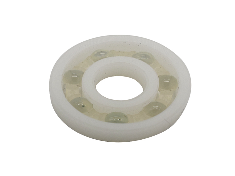
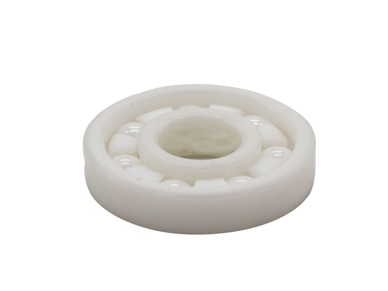
The full ceramic ball bearings listed below are supplied with rings and balls made from zirconium dioxide (ZrO2). These zirconia bearings are available as full complement (no cage) or with cages made from PTFE, PEEK or 316 stainless steel.
These are non magnetic, non-conductive and highly corrosion resistant to most chemicals although ZrO2 bearings are not recommended for prolonged contact with steam. Full complement bearings or those with a 316 stainless cage can be used up to 400°C while bearings with a PEEK or PTFE cage can cope with temperatures of up to 250°C. For temperatures below -70°C, PTFE or 316 stainless steel cages are preferred. Standard radial clearance for full ceramic bearings is C0 but other clearances can be supplied to order.
ZrO2 ceramic bearings are generally used for their extreme temperature capabilities, excellent corrosion resistance or non-magnetic properties. Other sizes can be supplied on request.

The Description of Ceramic Bearings:
Compared to steel, Ceramic ball Bearings have many specific advantages. They offer superior corrosion and heat resistance, higher dimensional stability, and lower density, which facilitate high speed. Ceramics are superior to steel in heat and corrosion resistance, and are lightweight and extremely hard as well. Consequently, ceramic rolling bearings can be used in environments where conventional steel bearings cannot. That is to say, the superiority of these bearings makes it possible that they can be applied in some special environments.
Firstly, they can be used in corrosive environments. Compared to stainless steel bearings, hybrid and all Ceramic Bearing lasted three and twenty times longer respectively. It is presumed that water readily adheres to silicon nitride and forms a better lubrication film, leading to extended bearing life.
Secondly, they can be performed in corrosive agents. Generally, silicon nitride has excellent corrosion resistance. However, corrosion resistance varies depending on the type and quantity of sintering additives, and certain corrosive agents decrease in hardness and flexural strength. In such situation, it is can be proved that the carbide-based ceramic bearings are the most effective.
Thirdly, they can be used in high-temperature vacuum. An all-silicon nitride Ball Bearing with a self-lubricating laminated cage (mainly composed of MoS2) and with MoS2-coated rings and balls proved superior in durability in a high-temperature vacuum environment. Compared with the hybrid bearings, the all-ceramic bearing was superior in both dynamic frictional torque and life.
Fourthly, they can be performed with poor lubrication. As ceramics are extremely hard and have outstanding wear resistance, they outperform other materials in bearing life without lubrication. According to a test, the steel bearing seized within a short period while the hybrid and all 627 Ceramic Bearings, though sustaining wear, did not. And the all-ceramic bearing sustained considerably less wear than the hybrid bearing, indicating that its endurance life is much longer.
Cermic Ball Bearing,Full Ceramic Bearing,Hybrid Ceramic Bearing,Self-Aligning Full Ceramic Ball Bearing
Shijiazhuang Longshu Mechanical & Electrical Equipment Trading Co., Ltd. , https://www.longsbearing.com