Based on the research of 3D CAD solid model feature extraction and platform-independent expression method, the STEP-based method is used to establish a scheme model and study the key technologies for the unified CAD/CAPP/CAFD integrated system. Identify the part information model that contains the part design features and include it in the STEP neutral file. The identification of geometric features, the mapping of geometric features to process features, and the combination of rule-based reasoning and case-based reasoning are used to solve the problem of process reasoning in feature-based process planning. Functional analysis and structural design of the system are carried out by means of object-oriented technology and UML, and the functional model and structural model of the integrated system are preliminarily established.
Foreword
The design results generated by the CAD system are output by the solid model. CAPP (Computer aided process planning) and CAFD (Computer Aided Fixture Design) can use the solid model as the information source, and the head directly generates production. Process procedures and tooling, fixture design results, make full use of CAD system design results and shorten product development cycle. The feature is an important milestone in the development of CAD 3D modeling technology. Identifying and utilizing feature information in process design and fixture design is the difficulty of reducing the exchange and sharing of geometric information, improving the intelligence of design and achieving the objective requirements of integration with CAD.
CAPP and CAFD are closely related to the characteristics of industry, enterprise and product objects, and have strong specificity. Research and development are generally carried out independently, lacking unified theory and implementation methods. One of the root causes is that it does not fully integrate with the design system, and can not fully utilize and share the 3D product design model. Therefore, the effective use of 3D design results, especially the use of 3D information at the feature level, is the key and foundation for the study of intelligent CAD/CAPP/CAFD integrated systems.
1 Establishment of part information model
1.1 Part information model structure analysis
The part information model content must cover information on part design, process, and manufacturing. Design information describes the target state of the part, including part geometry (geometry, topology, shape size, positioning size, dimensional accuracy, geometric tolerances, and roughness), and non-geometric information (material, physical, mechanical properties, etc.) ); process information generally includes processing processes, process content, and the like.
The concept of design features is used to abstract some of the interrelated design information elements. The use of features as part of the basic elements of integration in the part information model has become a consensus in this area of ​​research. There is an inevitable connection between design features and process characteristics. In the part information model, the design features are used as the source to generate process features, and the process features can be added to the part information model to become the basic information of the CAPP and CAFD systems.
The part information model should also contain the information of the part blank, the causal relationship between the blank and the design result. The CAPP system can derive the relationship between the two in the forward or reverse direction. The CAFD system is in transition with the blank and even the part. Related.
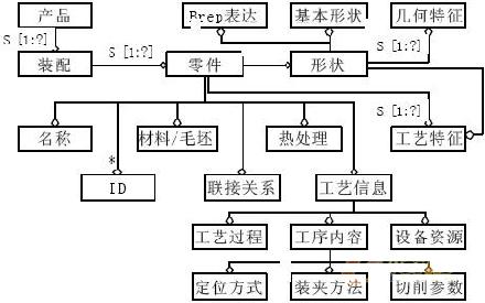
The part information model is built to comply with the STEP standard, and its EXPRESS-G diagram is shown in Figure 1.

Figure 1 part information model EXPRESS-G diagram
1.2 Implementation of the part information model
The data structure and content of the solid model output by different CAD platforms are different. The integration of specific CAD models with CAPP, CAFD, etc. results in the loss of openness and versatility of these downstream units. The part information model is implemented with a neutral standard data model (STEP model). Different CAD models generate a consistent neutral model through a dedicated pre-processing process.
Implementing the part information model with STEP needs to analyze the specific environment generated by the model file; one is done inside the CAD platform, and the other is done outside the CAD platform. Some CAD systems themselves can follow certain STEP protocol output models, simplifying the processing of design information. Some secondary development interfaces for CAD platforms allow post-processing module pairs to be generated and processed for neutral models. If the CAD platform does not introduce the concept of features, it must be specifically analyzed and studied for the structural characteristics of the entity model files in the platform. From the design basic elements and their constituent relationships in the entity model files, a specific feature recognition algorithm is proposed.
The design information extracted from the part solid model is added to the part information model and expressed in a neutral file (such as a STEP file), which can solve the heterogeneous problem of the solid model of different CAD platform parts. It can also solve the integration of CAD with CAPP, CAFD and other units. The versatility issue.
Next page
Microscope Camera ,Digital Microscope Camera,Camera Lucida Microscope,Microscope Eyepiece Camera
Ningbo Beilun Kalinu Optoelectronic Technology Co.,Ltd , https://www.nbyxmicroscope.com