Numerical Simulation of Non-Isothermal Transverse Jet of Thick-walled Tee in Nuclear Power Engineering Wu Hailing 5, Chen Tsengkuan 5, Luo Yishan 5, Mao Qing 2, Zhang Yixiong 1 (1. Xi'an Jiaotong University, Xi'an 710049, China; 1. China Nuclear Power Research Design Institute, Chengdu 610041) Calculation based on finite volume method, adopted! -! Turbulence model, calculation results and. For the sake of uniformity, the main stream and jet inlet parameters are denoted by subscripts 7 and respectively, respectively.
The geometric model and the coordinate system model are based on the filling nozzle on the chemical system of the nuclear reactor main system, and are modeled according to the 1/5 ratio, and the inner diameter of the main pipe! 80mm, the inner diameter of the jet tube! It is 14mm, the wall thickness is 10mm. The main entrance position is 8+ -7.14! The exit position is 8+21.4! The jet tube inlet position is 9+ 4.2! Its export is flush with the inner wall of the supervisor. According to the existing ones.
It can be seen that the calculation results are in good agreement with the experiment. The calculation is predicted to be in! /", there is a recirculation zone near 1 which is consistent with the results.
71994-2015d2aMir along the main and transverse e section of the fluid without 1 factor | degree 1, turbulent kinetic energy and temperature direction distribution / ww.cnki.net 3.2 transverse jet structure = 0.5 when the three-way pipe cross-flow calculation results are also painted in. It is found that since the diameter of the main pipe is much larger than that of the jet pipe, the curvature of the pipe wall has little influence on the lateral jet. The difference is only the condition of the round pipe, and the recirculation zone downstream of the jet is more obvious, and the downstream of the recirculation zone is more intense.
It is the contour-free distribution of the fluid-free downstream flow rate and the dimensionless temperature near the mixing zone on the symmetry plane. Comparing the two contour plots, it can be seen that using temperature to describe the jet trajectory is more reasonable than using the velocity, which can be explained by the physical similarity between heat transfer and mass transfer. It can be seen from the figure that the adherence of the jet is an important feature of the low flow rate compared to the transverse jet. Due to the compression of the jet by the mainstream, the jet has been obviously deflected in the downstream direction of the main flow, and the jet is strongly bent and bound in the adherent area. As the flow ratio increases, the jet deflection procedure decreases and the influence depth increases. And will gradually get out of the wall. It can also be seen that the temperature gradient of the fluid is the largest on the windward surface of the jet where the two fluids meet; the velocity gradient of the fluid is the largest in the downwind region of the exit hole; there is a significant velocity loss in the near wall region of the jet.
The fluid velocity distribution at the exit hole is extremely uneven, and the vertical velocity on the leeward side is much larger than the windward side; It is also possible to observe the unevenness of the temperature of the jet and the jet, which is mainly caused by the jet deflection and the heat conduction of the tube wall. As the flow rate ratio increases, the degree of deflection of the jet decreases, and the exit velocity and temperature tend to be uniform.
3.3 The temperature distribution of thick-walled pipe fittings is solved by the coupling of the fluid zone and the solid zone, and the temperature field of the component is obtained, which is the isotherm diagram of the pipe fitting on the symmetry plane. It can be seen that in the windward direction of the jet tube, the isotherm presents a divergent distribution centered on the intersecting lines in the two tubes, and the position with the largest temperature gradient is on the windward side of the inner intersecting line. From the analysis of the fluid temperature field, the temperature gradient of the fluid is the largest on the windward surface of the jet where the two fluids meet, which results in the maximum temperature gradient and thermal stress of the tube wall. The leeward is continuously mixed with the mainstream due to the jet. The temperature gradient of the fluid is much less than that of the wind. Therefore, the thermal stress on the windward side wall is greater than that of the leeward side under steady state conditions.
The dimensionless temperature contour transient thermal shock of the symmetry plane is predicted as the dimensionless vertical velocity distribution of the sections upstream of the exit hole in the jet tube on the symmetry plane. It can be seen from the figure that the non-uniformity of the jet-out 4 is another important feature of the low flow rate than the lateral jet. Due to the mainstream work, the dei jet is quickly deflected by the mainstream to hblishingH for the tube: transient state analysis of the steady-state condition of the transient rush zone: predicting the temperature characteristics of the component under transient conditions, and then analyzing the heat of influence The main factors of stress provide a theoretical basis for the optimal design of operating parameters and components.
Take the case where the jet begins to enter the mainstream. Before the jet is injected, the component temperature is the mainstream temperature. After the injection, due to the pressure of the main stream on the jet, the pressure on the windward side of the jet is much larger than that on the leeward side. The jet has deflected toward the leeward side in the jet tube, causing the boundary layer vortex ring in the jet tube to deform and migrate to the leeward side, eventually in the jet. The negative pressure zone formed by the mainstream flow on both sides falls off from the pipe wall and gradually develops into a three-dimensional vortex. The vortex directs the flow of the jet resulting in the violent energy, momentum and vorticity transport of the fluid, and as the jet bends, a strong turbulent zone is formed at the downwind of the jet. On the other hand, downstream of the jet tube, the thickness of the boundary layer of the main pipe wall begins to increase again, and the boundary layer near the injection perforation is the thinnest, and the wall surface heat exchange is extremely strong. In addition, when the jet is injected into the main pipe, the near-wall fluid temperature of the jet downwind main pipe is close to the jet temperature due to the adherence of the jet. Therefore, at the leeward side of the joint of the two tubes, the temperature of the inner wall will rapidly change from the initial main temperature to near the jet temperature, causing a transient thermal shock to the member.
In summary, the strong turbulence in the downwind zone, the re-growth of the boundary layer and the wall attachment property of the jet are the main factors leading to the transient thermal shock. The thermal shock danger zone is the inner wall position of the leeward side of the joint of the two pipes.
Selection of Jet Parameters The research in this paper is helpful to answer a question that engineers are very concerned about, that is, when the mainstream speed is constant, whether the thermal shock of the component can be reduced by changing the flow rate.
When the flow rate ratio is increased, the injected fluid occupies the jet tube at a faster speed, and the wall surface heat exchange of the jet tube is also more intense, so that the inner wall temperature approaches the jet temperature more quickly, and the thermal shock of the jet tube increases. . For the downstream supervisor, at low flow ratio (!"0. 02(1), as the jet velocity increases, the jet temperature is slowed by the mixing with the main stream, due to the wall attached property of the jet. The dimensionless temperature of the near-wall fluid is larger, that is, it is more affected by the jet, which is consistent with the experimental results, so the thermal shock to the downstream wall will be greater. The lateral jet from the higher flow ratio It can be seen that when the flow rate ratio reaches a certain range (!"2(10), the jet will be completely separated from the wall surface, the leeward area is the mainstream fluid, and the wall temperature of the downstream near zone is almost unaffected by the jet tube. The impact will increase dramatically and should not be used.
Conversely, when the flow rate ratio is reduced, the fluid mixing in the jet tube and the temperature change of the tube wall are slowed down at the time of incidence; in the downstream of the jet, since the core area of ​​the jet becomes smaller, the influence of the wall attachment property of the jet is also smaller, so appropriate reduction The small flow ratio is advantageous for the improvement of thermal shock.
However, it has been found by experiments that when the flow ratio is reduced to 0.02, the effect of turbulence on the jet is very large. There is a strong turbulent zone in the jet tube, and the fluid temperature and the wall temperature fluctuate greatly. Through numerical simulation, it is found that when "0", there is a vortex in the jet tube that is tangent to the main flow direction. When "0.02", the jet can not overcome the influence of the vortex, causing some mainstream fluid to be wound into the flow tube, and the vortex causes strong turbulence. The mixing with the hot and cold fluid produces a large temperature pulsation which may cause thermal fatigue damage to the component. Therefore, a flow rate ratio of 0.05 is a reasonable operating parameter.
5 Conclusion Based on the finite volume method, the turbulent flow model is used to simulate the non-isothermal transverse jet with the flow ratio of 0.05 and 0.5. The flow and heat transfer characteristics of the low flow ratio and the transverse jet are analyzed. The calculated results are compared with the experimental values. Good agreement.
The temperature distribution of the thick-walled three-way pipe fittings is obtained by the coupling calculation of the fluid zone and the solid zone. The influence of the flow structure on the component temperature distribution and thermal stress is investigated from the flow mechanism.
Through the analysis of the steady-state calculation results, the trend of component temperature under transient conditions is predicted. The main factors leading to the transient thermal shock of the components are: strong turbulence in the lower wind zone, re-growth of the boundary layer and jet flow. Wall attached.
The thermal shock conditions of the components with different flow ratios are discussed qualitatively, which provides a theoretical basis for the optimal design of operating parameters and components.
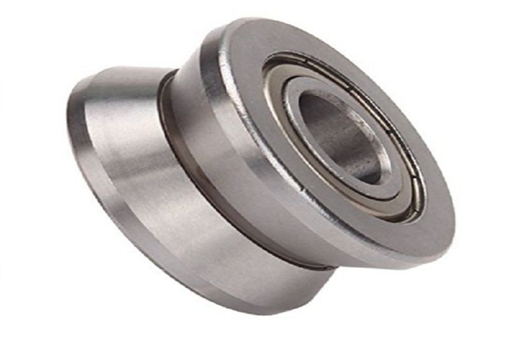
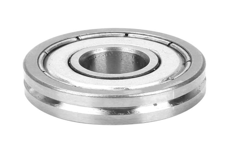
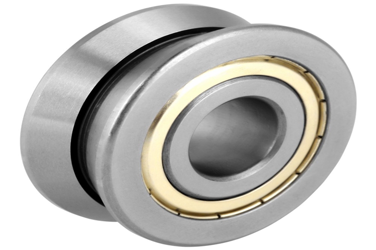
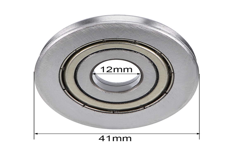
V Type Deep Groove Ball Bearing
V-groove bearings are precision ground, double row, angular contact bearings. The concentric and adjustable bushings provide a simple, effective means of adjusting the free play of the guide wheel system. Ideal for linear motion applications where the bearing runs along a rail or track as well as cable guide applications.
Types: V-groove, U-groove, G-groove, guide wheel
Configurations: Sealed, Shielded, open
Materials: 52100 steel, stainless steel
NPB offers concentric and adjustable configurations, single and double row, in both inch and metric sizes from stock.
Typical applications include:
• Robotics
• Material handling
• Door actuation
• Pulleys
• Specialty applications


V Type Deep Groove Ball Bearing,High Speed V Groove Bearing,Miniature V Deep Groove Bearing,High Speed V Groove Ball Bearing
Shijiazhuang Longshu Mechanical & Electrical Equipment Trading Co., Ltd. , https://www.longsbearings.com